Reverse Engineer: Part Three (Improved Renders and Axo Drawings).
Presentation and Files:
Process For Adding Some Final Details:
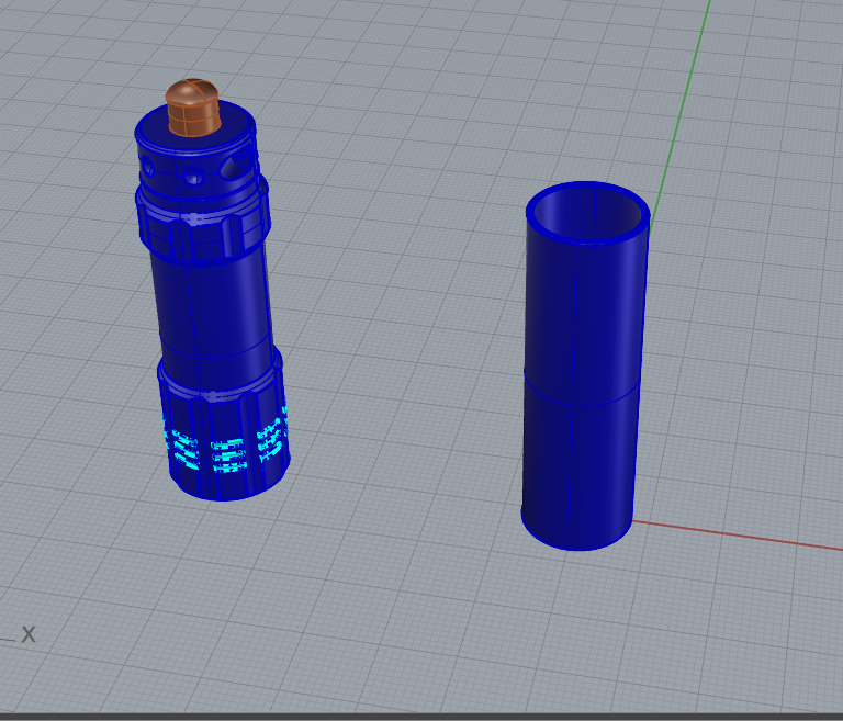
Decided to redo the lower part of the cap because it actually isn't threads like the upper part, but just bumps. So I used the unroll and flow along surface commands.
Made a cylinder the size of what I needed because unroll doesn't like the tube shape.
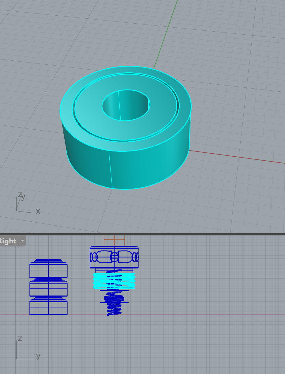
Making sure I have the right number of bumps and the right spacing.


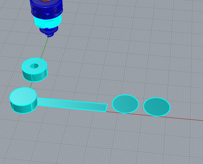
Mini render to check progress

Then I did the same thing to be able to place the Eddie Bauer logo as well.
Same thing here - making the right-sized cylinder that I will be able to unroll.

On the unrolled surface, I made guide marks to be able to properly place the logo so that it doesn't overlap with anything or do anything funky.


Ta-da!

Renders: Before Tutorial


Renders: After Tutorial:


Process with Axo Drawing:
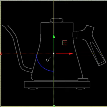
Started with the basic lines and set up for step one.
Converted it to the drawing with the "Make 2D" command.
Then started making the next step.


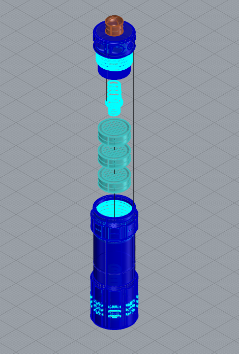
Decided it would be good to show which way you screw it together (because lord knows that screwing things in, in the proper direction, can be annoying sometimes).

The drawings - version 1.
Two things - the under drawings (the gray lines) make the drawings quite cluttered and the photo that I used for the logo only shows the border of the image and not the logo - so I had to make sure that was hidden.


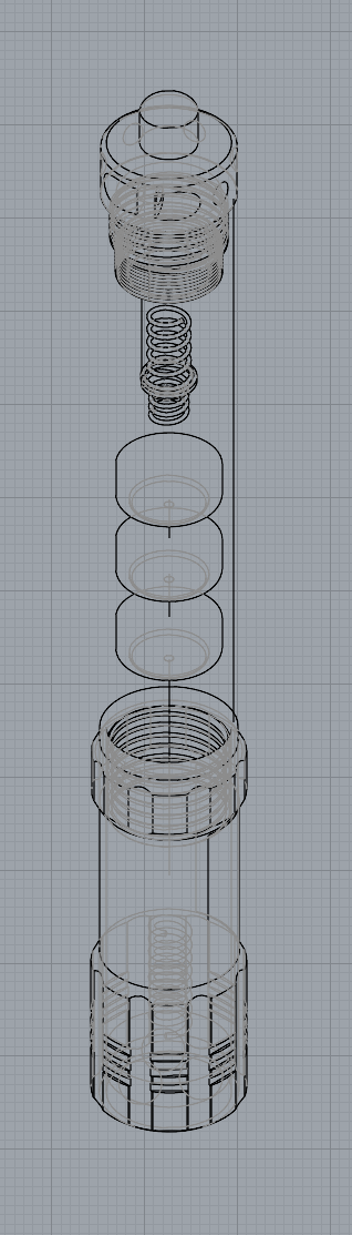
Attempt one at setting up the axo drawing.
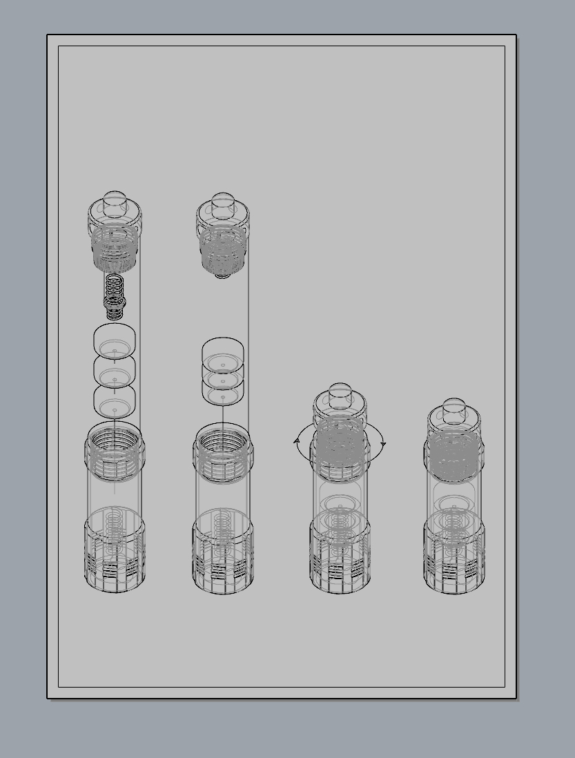
Then I redid it so that it didn't have the gray lines that show the stuff you can't see. It makes it a lot cleaner and is unnecassary for this drawing.


Final:


Comments
Post a Comment